Evening Edition · Riggers · Intermediate · Advanced · 10-minute read
What you will learn: calculate the ideal static load carried at two lift lines when a known center of gravity is off center, check the answer with force and moment balance, and recognize where the paper model stops.
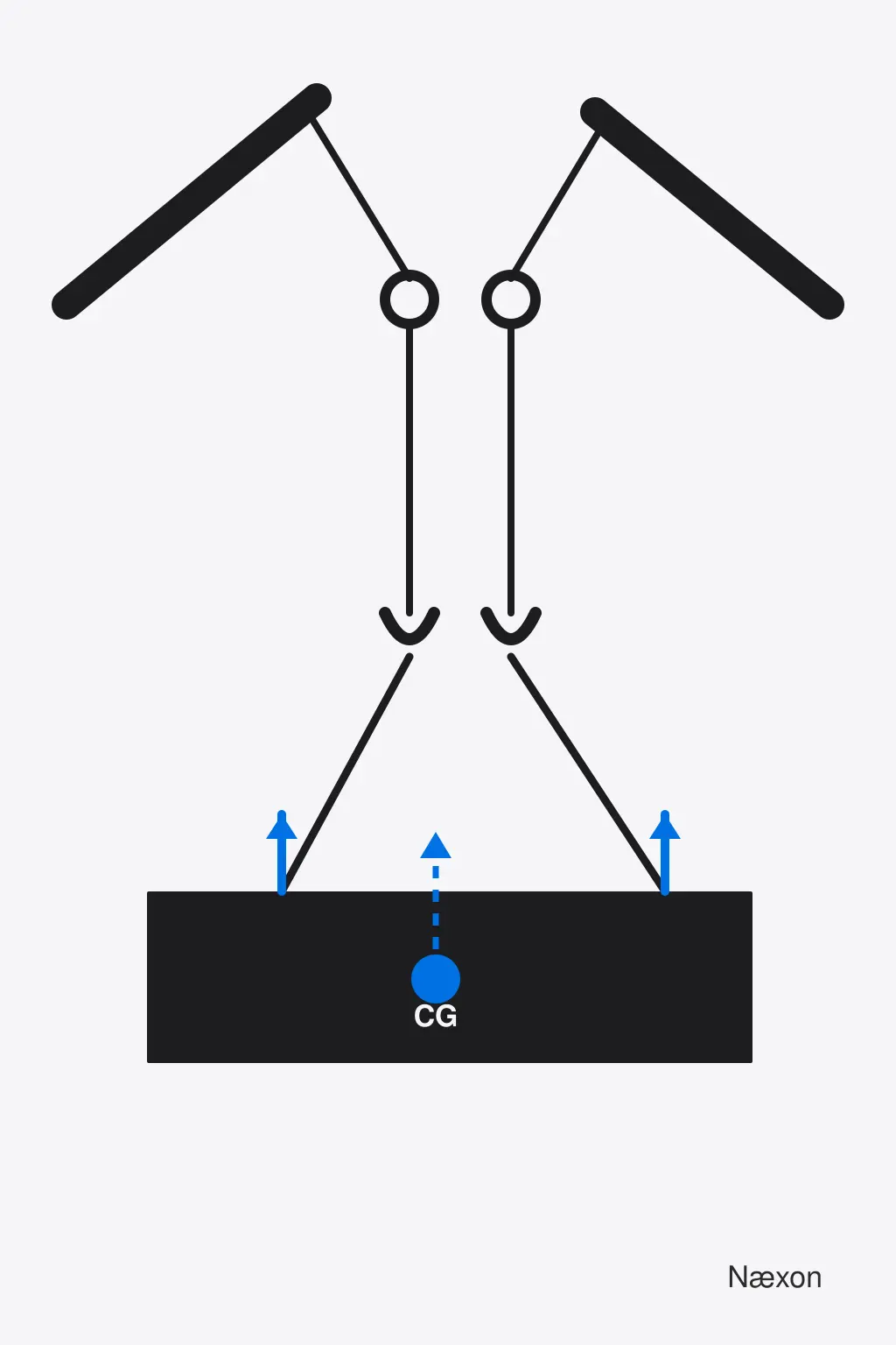
A long skid is ready to move with one crane at each end. The total weight is known, but the heavy equipment is crowded toward one side. Calling the lift “half and half” would be simple—and wrong. The lift line closer to the center of gravity must carry more of the static vertical load.
This lesson develops that relationship as a paper calculation. It is a deeper application of center-of-gravity fundamentals for rigging. It does not authorize a multiple-crane lift. A real operation requires the controlling engineered or qualified-person plan, the correct crane configurations and load charts, verified weights and geometry, communication, supervision, and site procedures.
Why an off-center center of gravity changes the share
For a stationary body in vertical equilibrium, the upward reactions must equal the downward weight. The turning effects, called moments, must also balance. A moment equals a force multiplied by its perpendicular distance from a chosen reference point.
Model the lifted assembly as one rigid body supported by two vertical lift lines. Let W be its total modeled weight, RL the left reaction, and RR the right reaction. Let a be the horizontal distance from the left lift line to the center of gravity, b the distance from the center of gravity to the right lift line, and L = a + b the distance between lift lines.
The vertical-force equation is:
RL + RR = W
Taking moments about the left lift line removes RL from that equation:
RR × L = W × a
Therefore:
RR = W × a ÷ L
Taking moments about the right lift line gives the companion equation:
RL = W × b ÷ L
Notice the crossed distances. The left reaction uses the distance from the center of gravity to the right support, while the right reaction uses the distance to the left support. That relationship makes physical sense: as the center of gravity moves closer to the left lift line, b becomes a larger share of L, so the left reaction increases.
Worked example: a 60,000-pound assembly
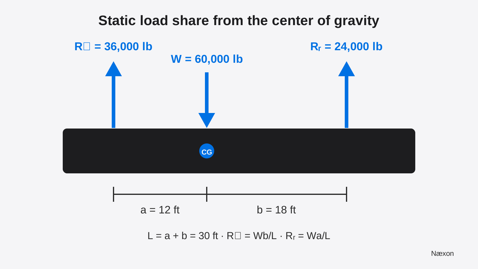
Assume an illustrative rigid assembly weighs 60,000 lb. Its verified center of gravity lies between two vertical lift lines. The left lift line is 12 ft from the center of gravity, and the right lift line is 18 ft from it. The lines are therefore 30 ft apart.
These dimensions and weights are invented for training. The model assumes a stationary, level body; vertical, parallel lift lines; fixed lift points; known center of gravity; negligible deflection; and no wind, acceleration, shock, side loading, fluid movement, load transfer, or geometric change. A real lift plan must address the conditions that actually exist.
Define the values:
W = 60,000 lb; a = 12 ft; b = 18 ft; L = 12 ft + 18 ft = 30 ft.
Calculate the right reaction:
RR = W × a ÷ L = 60,000 lb × 12 ft ÷ 30 ft = 24,000 lb.
The feet cancel, leaving pounds. Now calculate the left reaction:
RL = W × b ÷ L = 60,000 lb × 18 ft ÷ 30 ft = 36,000 lb.
No rounding is needed in this example. The static modeled split is 36,000 lb at the left lift line and 24,000 lb at the right lift line, or 60 percent and 40 percent of the total modeled weight.
First check the force balance: 36,000 lb + 24,000 lb = 60,000 lb. Then check moments about the left lift line. The right reaction produces 24,000 lb × 30 ft = 720,000 lb-ft. The assembly weight produces 60,000 lb × 12 ft = 720,000 lb-ft. The moments match.
A reasonableness check reaches the same conclusion without arithmetic. The center of gravity is closer to the left lift line, so the left share must exceed one-half and the right share must be below one-half. A 36,000/24,000 result fits that physical expectation. An answer of 24,000 lb left and 36,000 lb right would reveal that the moment arms were assigned backward.
The reactions in this simplified model are not complete crane-capacity answers. Each crane must be evaluated in its actual configuration, radius, boom length, quadrant, reeving, ground condition, and manufacturer chart. The applicable plan also accounts for hook blocks, rigging, lifting devices, attachments, and any required deductions. Review gross versus net crane capacity before comparing a calculated share with a chart.
The common wrong approach: divide by two
Dividing by two works only when the modeled center of gravity is exactly midway between equal-height vertical supports in the stated static model. It is not a safe default. An off-center center of gravity changes the reactions even when the load looks geometrically symmetrical.
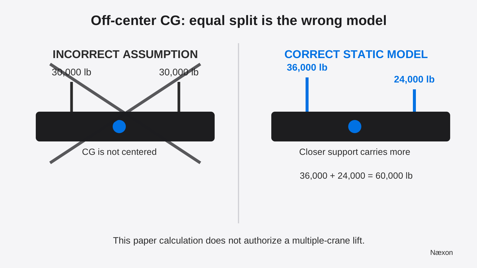
The incorrect approach fails because it satisfies the total-force equation but not the moment equation. Two 30,000-pound reactions add to 60,000 pounds, yet their combined turning effect does not balance a weight acting away from midspan. Checking only the sum can therefore hide a serious distribution error.
A correct result has two visible qualities: the reactions add to the modeled weight, and the moments balance about either support. Both checks are necessary. Use the Næxon Numerus calculator for arithmetic if useful, but keep the diagram, variables, units, and assumptions with the result so a qualified reviewer can reproduce it.
A practical planning check
- Confirm the authorization boundary. Treat a two-crane lift as a planned operation directed under the employer’s governing requirements. Do not turn this lesson into a field lift plan.
- Verify the modeled weight. Use an approved source or recognized calculation. Identify whether the stated weight includes retained contents, temporary steel, lifting beams, rigging, and attachments.
- Locate the center of gravity. Use approved drawings, weight reports, engineering information, or the method specified by the qualified person. Do not infer it from the geometric center.
- Identify the support lines. Measure the horizontal distance between the vertical lines of action used in the model, not the distance between crane carrier centers or boom tips.
- Draw and label the free-body diagram. Show W, RL, RR, a, b, and L. If the actual arrangement cannot be represented by this simple diagram, stop and escalate.
- Calculate and check. Solve both reactions, confirm their sum, and verify one independent moment equation.
- Compare with the complete plan. The qualified lift plan governs crane selection, capacity deductions, rigging, sequence, permitted load transfer, communication, test-lift controls, exclusion zones, and stop conditions.
Why the numbers can change during the lift
The equations describe one ideal static geometry. Real load sharing can change when one crane hoists faster, one boom deflects differently, the load rotates, the lift lines leave vertical, a support point changes elevation, the structure flexes, or the center of gravity moves. Liquids and loose internal material can shift. Wind and acceleration add forces not represented by the paper model.
That is why a static 60/40 result must not be treated as a permanent mechanical equalizer. A multiple-crane plan specifies how movements are coordinated and how the load is monitored. If the observed geometry, line direction, instrument indications, or load behavior differs from the plan, the correct response is to stop under the lift director’s procedure—not to improvise a new split while the load is suspended.
Sling-leg tension is a related but separate calculation. The support reaction is the vertical share delivered at a lift line; angled slings can create larger tension along the sling. Use the verified reaction as an input only when the approved rigging model calls for it, then apply the correct geometry as explained in the sling-length and rise method.
Troubleshooting a calculation that does not make sense
If the reactions do not add to W, recheck transcription, units, and arithmetic. If both reactions are positive but the farther support carries more, verify that a and b were not swapped. If a calculation produces a negative reaction, the assumed center of gravity lies outside the two-support span or the model is otherwise inconsistent; do not treat the negative value as a usable crane load.
If measured load indicators disagree materially with the planned distribution, do not average the displays or command one operator to “take a little more” without the plan’s direction. Possible causes include incorrect input weight or center of gravity, geometry change, indicator limitations, crane setup differences, structural flexibility, or unplanned load transfer. Land or secure the load as the authorized plan directs and escalate.
If the load tilts or begins to rotate, the planned relationship between the hook lines and the combined center of gravity may not match reality. Review what riggers check when a suspended load starts rotating. Never enter the fall zone, side-pull, or make an improvised connection to force the load level.
Common mistakes
Frequent errors include using the geometric midpoint as the center of gravity, measuring from the crane centerline instead of the lift line, omitting lifting devices from the weight ledger, swapping the opposite moment arms, checking only that the reactions add to the weight, and comparing an ideal support reaction directly with a crane’s rated capacity without all required deductions and conditions.
Another mistake is assuming a clean static calculation predicts every stage of the lift. The calculation is a planning tool for one defined geometry. It does not address synchronization, dynamic effects, line angle, boom deflection, ground support, chart capacity, communication, or structural adequacy of the load and lift points.
Field Rules
- Never assume 50/50 unless the verified model supports it.
- The support closer to the center of gravity carries the larger static share.
- Check both force balance and moment balance.
- Measure between lines of action, not convenient equipment landmarks.
- Keep the weight basis, units, geometry, and assumptions with the calculation.
- A qualified-person lift plan and lift director control a multiple-crane operation.
Knowledge Check
- A 40,000-pound rigid load has its center of gravity 8 ft from the left lift line and 12 ft from the right. What are the ideal static reactions?
- Two calculated reactions add to the total weight. Is that alone enough to validate the distribution?
- Why does the left reaction formula use the distance from the center of gravity to the right lift line?
- During a coordinated lift, one indicator departs from the planned share. What is the correct first principle?
Answers and explanations
1. The span is 20 ft. Left reaction = 40,000 lb × 12 ft ÷ 20 ft = 24,000 lb. Right reaction = 40,000 lb × 8 ft ÷ 20 ft = 16,000 lb. The closer left support carries more. 2. No. The moment equation must also balance; an equal split can have the correct total and still be wrong. 3. Moments are taken about the opposite support, so the force uses the perpendicular distance to that moment center. 4. Follow the lift director’s stop and recovery procedure. Do not improvise load transfer from the cab or fall zone.
Practical Exercise
On paper, draw a 75,000-pound rigid load between two vertical lift lines 25 ft apart. Place the center of gravity 10 ft from the left line and 15 ft from the right. Calculate both static reactions, verify their sum, and check moments about the left lift line.
Expected result: RL = 75,000 × 15 ÷ 25 = 45,000 lb and RR = 75,000 × 10 ÷ 25 = 30,000 lb. Their sum is 75,000 lb. The moment check is 30,000 lb × 25 ft = 750,000 lb-ft and 75,000 lb × 10 ft = 750,000 lb-ft. This is a supervised training calculation, not an approved lifting procedure.