Evening Edition · Electricians · Apprentice to Intermediate · Print Reading · 10-minute read
What you will learn: Trace a basic three-wire motor-starter rung through Start, seal-in, Stop, and overload states; build a state table; and use the drawing to separate a no-start fault from a no-seal fault.
The motor runs only while the operator holds the Start button. The instant that finger comes off, the contactor drops out. Replacing the Start button would be a guess. The more useful question is: which path should carry coil current after Start returns open?
This lesson turns a familiar ladder rung into a state-by-state print-reading method. It goes beyond identifying contact symbols by showing how one contact changes the path that keeps the same coil energized. The earlier lesson on normally open and normally closed contacts is the best prerequisite if the symbols are not yet automatic.
This is a paper-based training exercise, not authorization to work energized. Real motor-control circuits may include additional permissives, safety devices, PLC outputs, remote commands, timers, and multiple voltage sources. Approved drawings, equipment instructions, the employer’s electrical-safety and hazardous-energy-control programs, and qualified supervision control field work.
What “three-wire control” means here
In a conventional electromechanical three-wire control scheme, momentary Stop and Start devices command an electrically held contactor or starter. The third functional path is the contactor’s own normally open auxiliary contact, commonly called a holding or seal-in contact. The exact conductors and terminals vary; “three-wire” describes the control arrangement, not permission to assume a universal terminal layout.
The simplified rung in Figure 1 runs from control source L1 through a normally closed Stop contact and a normally closed overload contact. A parallel branch then offers two ways to reach coil M: the normally open Start contact or the normally open M auxiliary contact. The return side of M connects to L2.
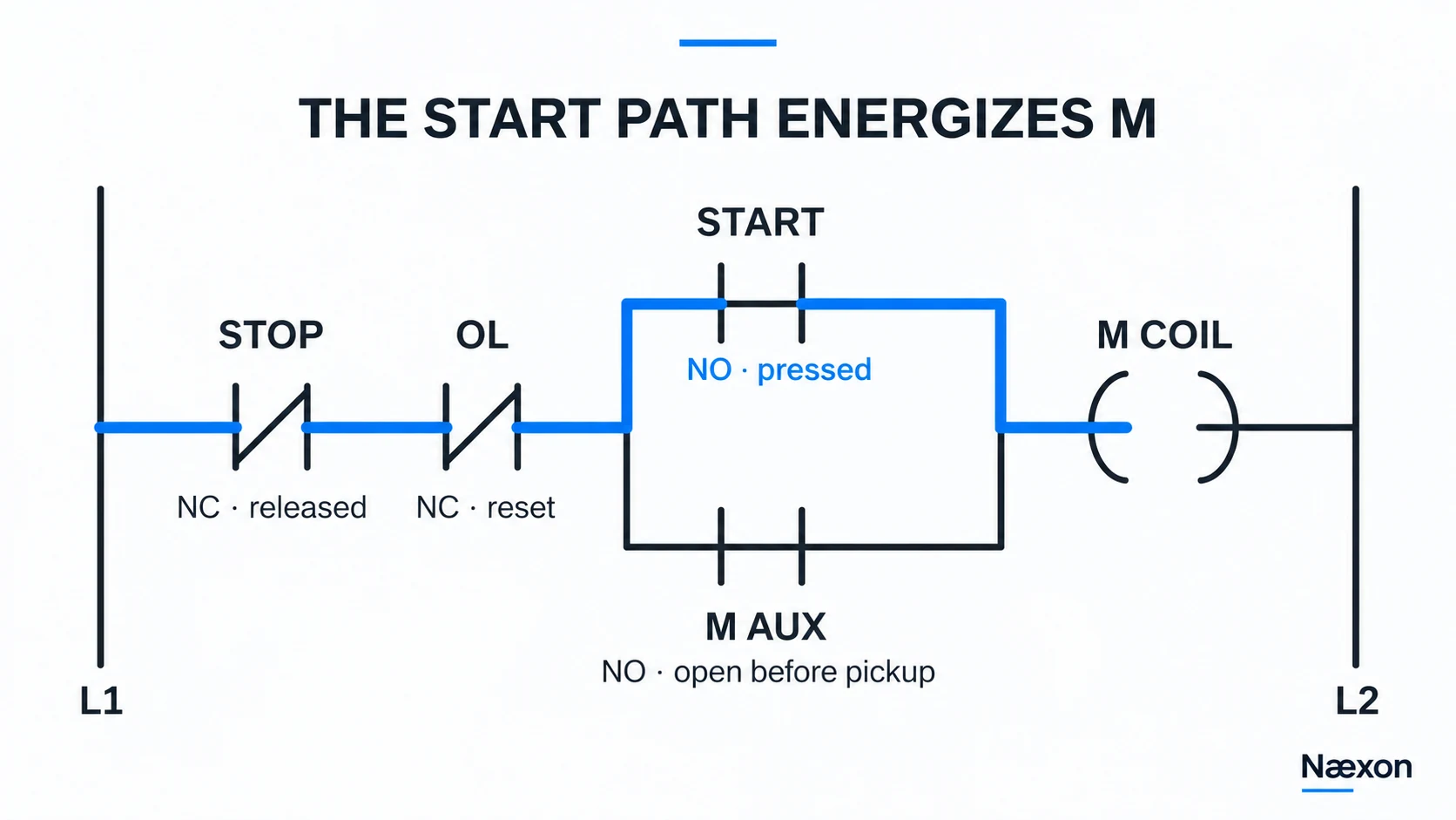
Stop and overload are upstream of both parallel branches. That placement matters: when either series contact opens, it interrupts both the Start path and the seal-in path. The parallel branch does not bypass them.
Trace the rung in three states
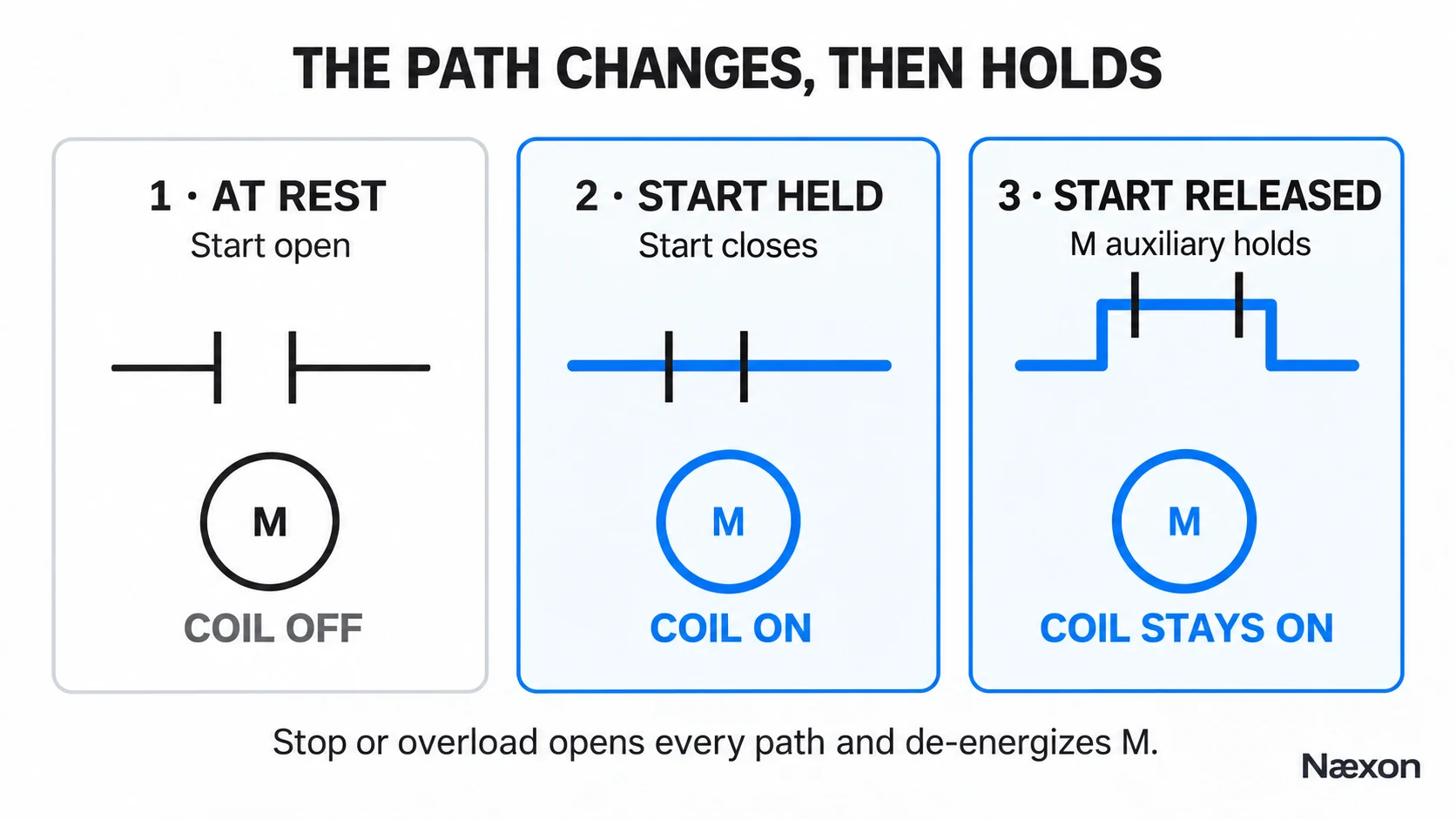
At rest, Stop and the overload contact are closed in this training example. Start is open. M is de-energized, so M’s normally open auxiliary contact is also open. Both parallel branches are open, and there is no complete path to the coil.
While Start is pressed, the Start contact closes. Current can pass through Stop, overload, Start, and coil M. M energizes and operates its associated contacts. Its main power contacts close as designed, and its normally open auxiliary contact closes across the Start branch.
When Start is released, the Start contact returns open. The coil does not need that branch anymore because the closed M auxiliary contact provides the parallel path. Coil M therefore remains energized. Pressing Stop or opening the overload contact breaks the series path, de-energizes M, and lets the M auxiliary return open. A later restart requires another Start command.
Build a state table before naming a fault
A state table forces each assumption into the open. For this conceptual rung, record whether each device is conducting and whether M should be energized. Do not use “on” and “off” alone; state whether a contact is open or closed and whether its controlling device is operated.
With all devices in their reset reference condition, the expected row is: Stop closed, overload closed, Start open, M auxiliary open, M coil de-energized. During the Start command: Stop closed, overload closed, Start closed, M auxiliary transitions closed as M picks up, and M energizes. After Start is released during normal running: Stop closed, overload closed, Start open, M auxiliary closed, and M remains energized.
For a Stop command, Stop opens and M de-energizes regardless of the parallel branch. For an overload trip, the overload contact opens and M de-energizes. The overload device and reset method must match the actual equipment documentation; this lesson does not prescribe reset behavior.
Worked example: runs while Start is held, then drops out
Assume the observed sequence is exactly this: the contactor picks up promptly while Start is held, remains stable while the button stays pressed, and drops out immediately when Start is released. The correct drawing is available, and the circuit is the simplified arrangement in Figure 1.
First compare the symptom with the state table. Pickup proves that a complete path existed through the common series devices, the Start branch, and the coil at that moment. It does not prove every connection is healthy under every condition, but it narrows the logic.
Next identify the transition that failed. Releasing Start intentionally opens the Start branch. The only path expected to remain is through the M auxiliary branch. If M drops at that exact transition, the first drawing-based suspicion is the seal-in path: the auxiliary contact may not have closed, its field connection may be open, its wire may be landed incorrectly, or the actual device/tag may not match the print.
The reasonableness check is behavioral. If the Stop or overload path were already open, the coil could not stay energized even while Start was held. If the coil itself were open, it could not pick up. The symptom follows the branch change, so the seal-in branch deserves inspection before unrelated parts are replaced.
This conclusion is a troubleshooting direction, not a final diagnosis. Establish the approved safe work condition before opening, continuity-testing, tightening, or replacing components. Compare device tags, terminal designations, wire numbers, contact action, and the exact manufacturer documentation. Escalate if the installed circuit differs from the approved drawing or if a safety function is involved.
No-start and no-seal are different fault families
A no-start symptom means M never energizes when Start is commanded. On paper, possible open points include the control source or protective device, Stop, overload, another series permissive, the Start contact, wiring, or the coil. Mechanical obstruction or a mismatched device can also prevent pickup even when the control logic calls for it.
A no-seal symptom means M energizes through Start but cannot remain energized after Start is released. That timing directs attention to the auxiliary holding branch and to anything that changes when the contactor operates. The existing lesson on motor-contactor chatter covers a different symptom: unstable repeated pickup and dropout, often requiring the qualified electrician to compare actual coil conditions with device requirements.
A will-not-stop report demands caution. It may involve a welded or bypassed contact, incorrect wiring, a maintained remote command, a mechanical problem, or a different control path. Do not treat opening an enclosure or operating another control device as the default response. Use the site’s emergency, isolation, and escalation procedures.
A practical print-reading method
- Confirm the drawing. Check the equipment tag, sheet, revision, legend, and control-voltage source. A correct-looking generic ladder is not the approved circuit.
- Box the coil and its controlling contacts. Find M and every contact tagged M. Separate main contacts from auxiliary contacts.
- Mark common series devices. Identify contacts that every branch must pass through, such as Stop, overload, and documented permissives.
- Mark parallel branches. Trace the momentary Start path and the seal-in path independently from their branch point to their reunion point.
- Write the reference state. Record each contact as open or closed with its controlling device de-energized or unoperated.
- Advance one event at a time. Press Start, energize M, change every M contact, then release Start. Do not change several device states at once.
- Compare the observed transition. Identify the exact event after which field behavior departs from the state table.
- Choose the safe verification. Follow the approved procedure for isolation and testing. The drawing selects the branch to examine; it does not waive electrical safe-work requirements.
For broader context on how power reaches the MCC and starter, review how to read an electrical one-line diagram. A one-line maps distribution; the control schematic in this lesson explains the starter’s logic.
Troubleshooting without guessing
If M never picks up, do not jump straight to the contactor. Confirm the correct drawing, control source, protective devices, contact states, and every series condition. An overload contact shown normally closed may be open because the overload is tripped, defective, incorrectly reset, or not the device represented by the assumed tag.
If M picks up but will not seal, compare the auxiliary-contact tag and physical contact block with the drawing. Verify that the holding contact is truly normally open in the de-energized reference state and that it is mechanically operated by M. A spare auxiliary from another device can look similar on the page while controlling a different path.
If M stays sealed after Stop is operated, stop and escalate under the site procedure. Look for an alternate parallel command on the approved drawing rather than assuming the Stop contact alone controls every path. Never use a pushbutton, selector switch, PLC command, or inferred open contact as proof of isolation.
If repeated cycling, overheating, odor, damaged insulation, arcing, or protective-device operation is present, discontinue attempts and escalate. Manufacturer troubleshooting information may identify poor control contacts, low coil voltage, an incorrect coil, mechanical obstruction, or other equipment-specific causes. Do not convert a print-reading exercise into unsupervised energized diagnosis.
Common mistakes
The most common drawing error is tracing through Start and stopping at the coil. That explains pickup but not what happens after Start returns open. Another mistake is treating the seal-in branch as a bypass around Stop or overload; in the conventional rung, those series contacts remain common to both branches.
Readers also forget that M’s auxiliary contact changes state only after M operates, confuse a contact’s reference symbol with its present state, or assume identical labels mean identical terminal numbers. The correct print, device documentation, and field identification decide those details.
Field Rules
- Trace the Start branch and the seal-in branch separately.
- Keep Stop, overload, and other common series devices common in your logic.
- Change every contact tagged M when coil M changes state.
- Use the failed transition to choose the next branch to inspect.
- A control command is not energy isolation.
- Stop when the installed circuit, device tag, or safety function does not match the approved documents.
Knowledge Check
- In Figure 1, both buttons are released, the overload is reset, and M is de-energized. Which two contacts prevent a complete path through the parallel branch?
- M energizes while Start is held but drops out when Start is released. Which branch should the drawing direct you to examine first, and why?
- The overload contact opens while the starter is running. What happens to M and its auxiliary contact?
- A contactor does not energize at all when Start is pressed. Can the symptom alone prove that the coil is defective?
- Stop has been pressed and the contactor is open. Does that establish an electrically safe work condition?
Answers and explanations
1. The released Start contact is open, and the M auxiliary is open because M is de-energized. Either open branch prevents current through that branch. 2. Examine the M auxiliary seal-in branch first because the failure occurs exactly when Start intentionally opens and the auxiliary path should take over. 3. Opening the common series overload contact de-energizes M. M’s normally open auxiliary then returns open, so the circuit requires a new valid Start sequence after the overload condition and reset are handled under the approved procedure. 4. No. Any open point in the control path, an unavailable source, a mechanical problem, a mismatched device, or the coil itself could produce no pickup. The print organizes the checks. 5. No. A Stop pushbutton is a control device, not an energy-isolating device. Follow the approved isolation, lockout/tagout, stored-energy, and verification process.
Practical Exercise
Print Figure 1 or redraw it on paper. Make five columns labeled At Rest, Start Held, Running After Release, Stop Pressed, and Overload Open. Add rows for Stop, overload, Start, M auxiliary, and M coil. Fill each contact with open or closed and the coil with energized or de-energized. Then highlight the complete path, if one exists, in each column.
Your check should show M de-energized at rest; energized through Start while Start is held; energized through M auxiliary after Start is released; and de-energized when either Stop or overload opens. In the last two states, M auxiliary returns open after M drops out. Keep the exercise on paper or use only a purpose-built, supervised, de-energized training board.