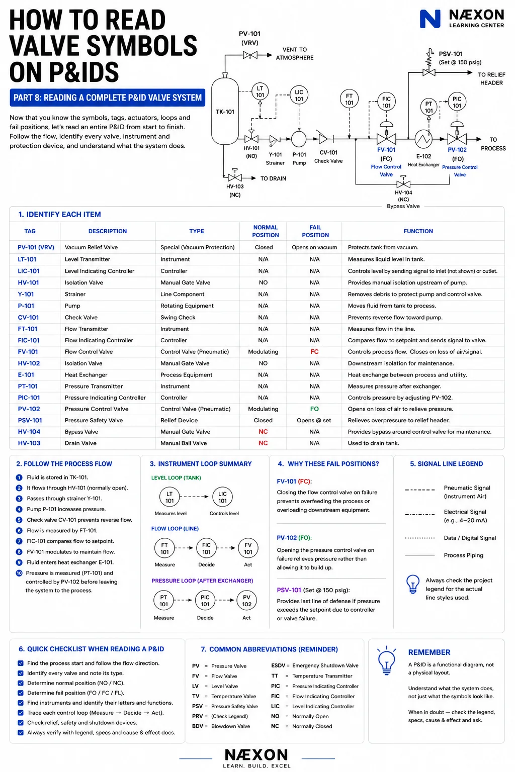
How to Read Valve Symbols on P&IDs — Part 8: Reading a Complete P&ID Valve System
Part 8 combines the series into a complete P&ID example with a tank, pump, control valves, heat exchanger, instruments, and relief protection.
Read article →NÆXON INDUSTRIES
220 articles
Part 8 combines the series into a complete P&ID example with a tank, pump, control valves, heat exchanger, instruments, and relief protection.
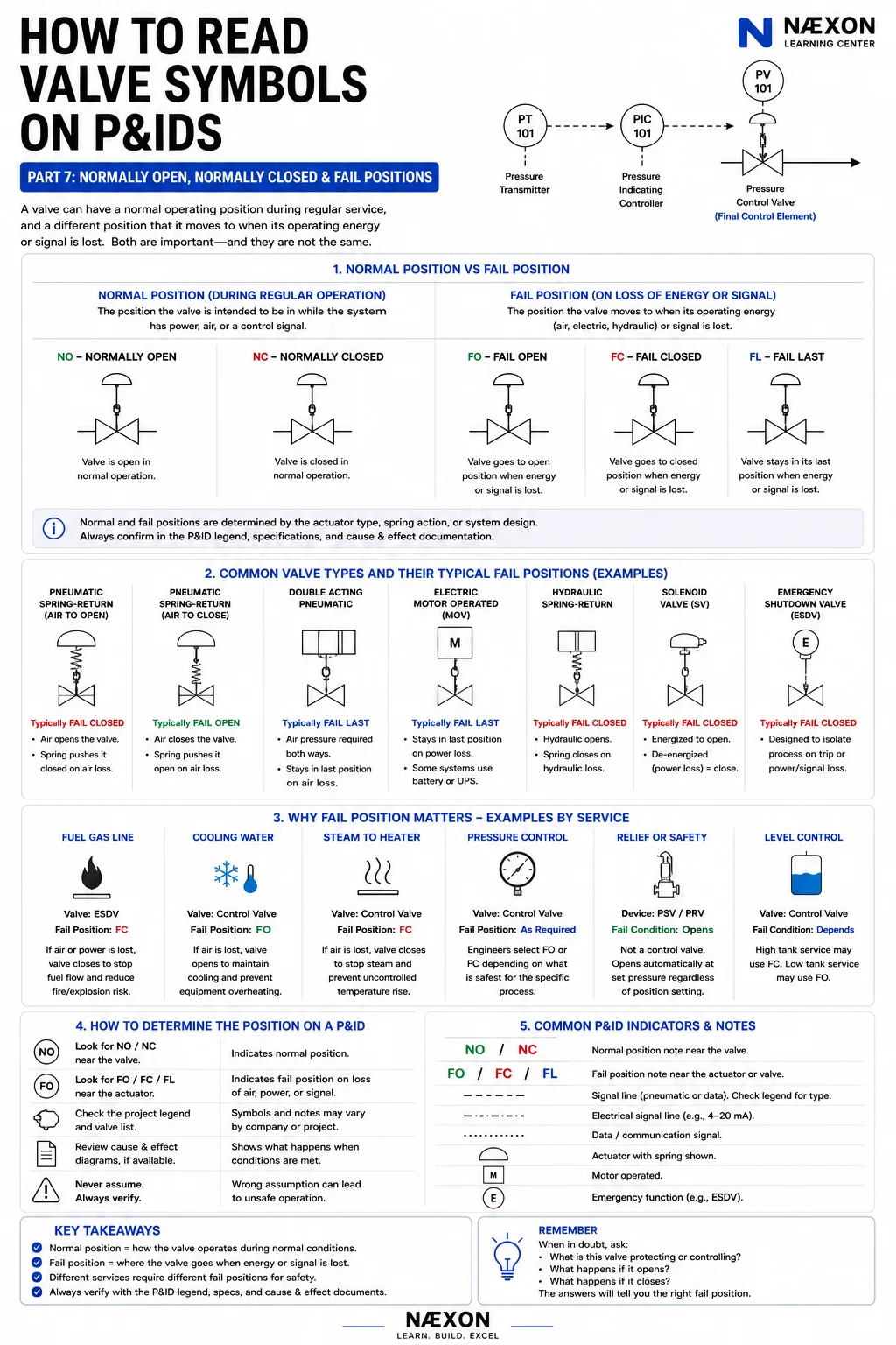
Read article →Part 7 explains normal operating position and the position an actuated valve takes after loss of energy or signal.
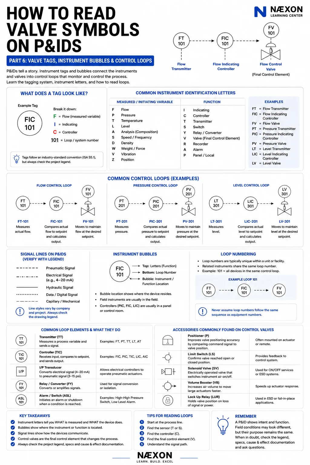
Read article →Part 6 connects valve tags with transmitters, controllers, final control elements, and the signal lines between them.
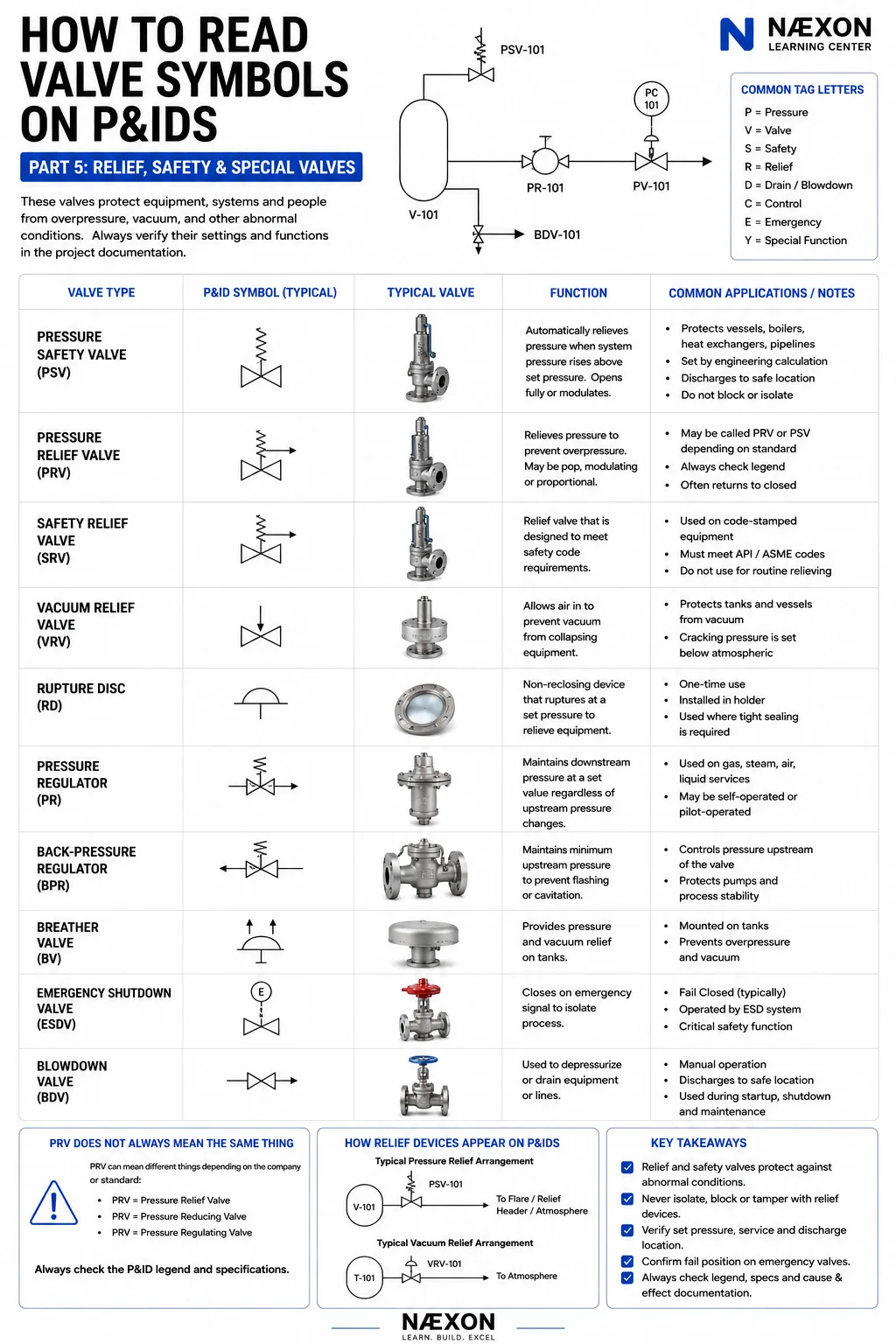
Read article →Part 5 covers symbols used to protect equipment, manage abnormal pressure, and move processes toward safer states.
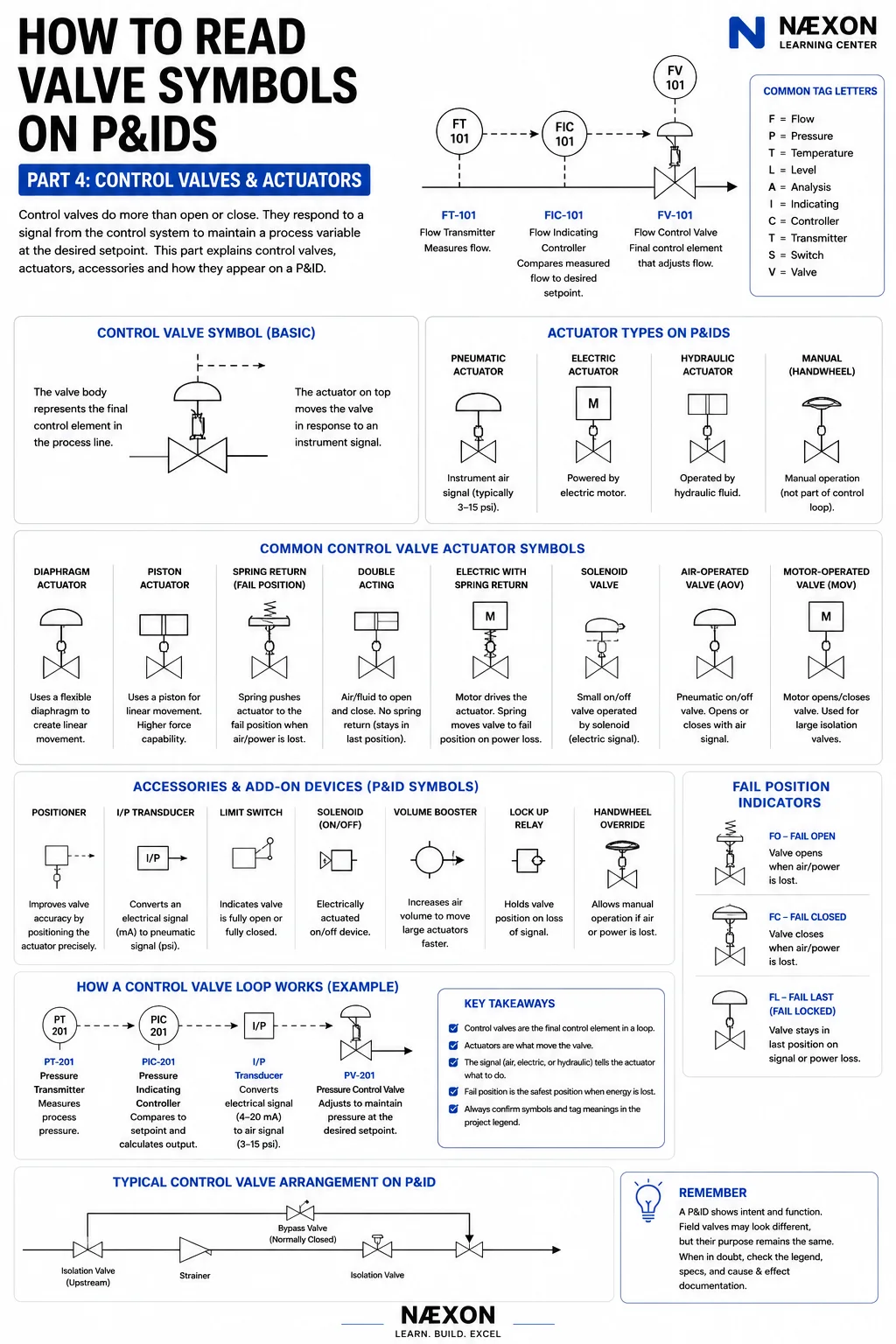
Read article →Part 4 explains control valves as final control elements and shows how pneumatic, electric, and hydraulic actuators fit the loop.
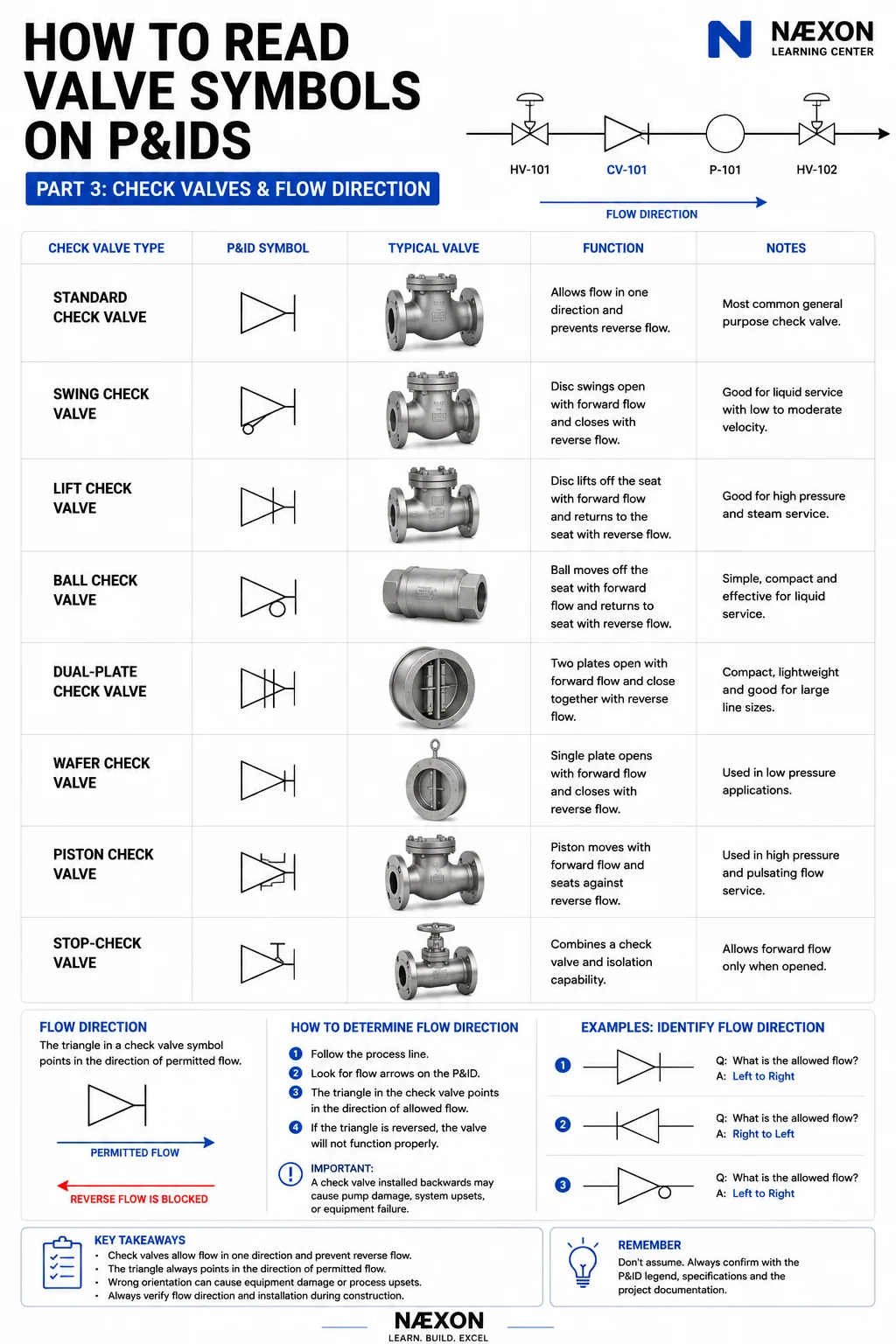
Read article →Part 3 introduces check-valve symbols and the importance of tracing process flow direction on a P&ID.
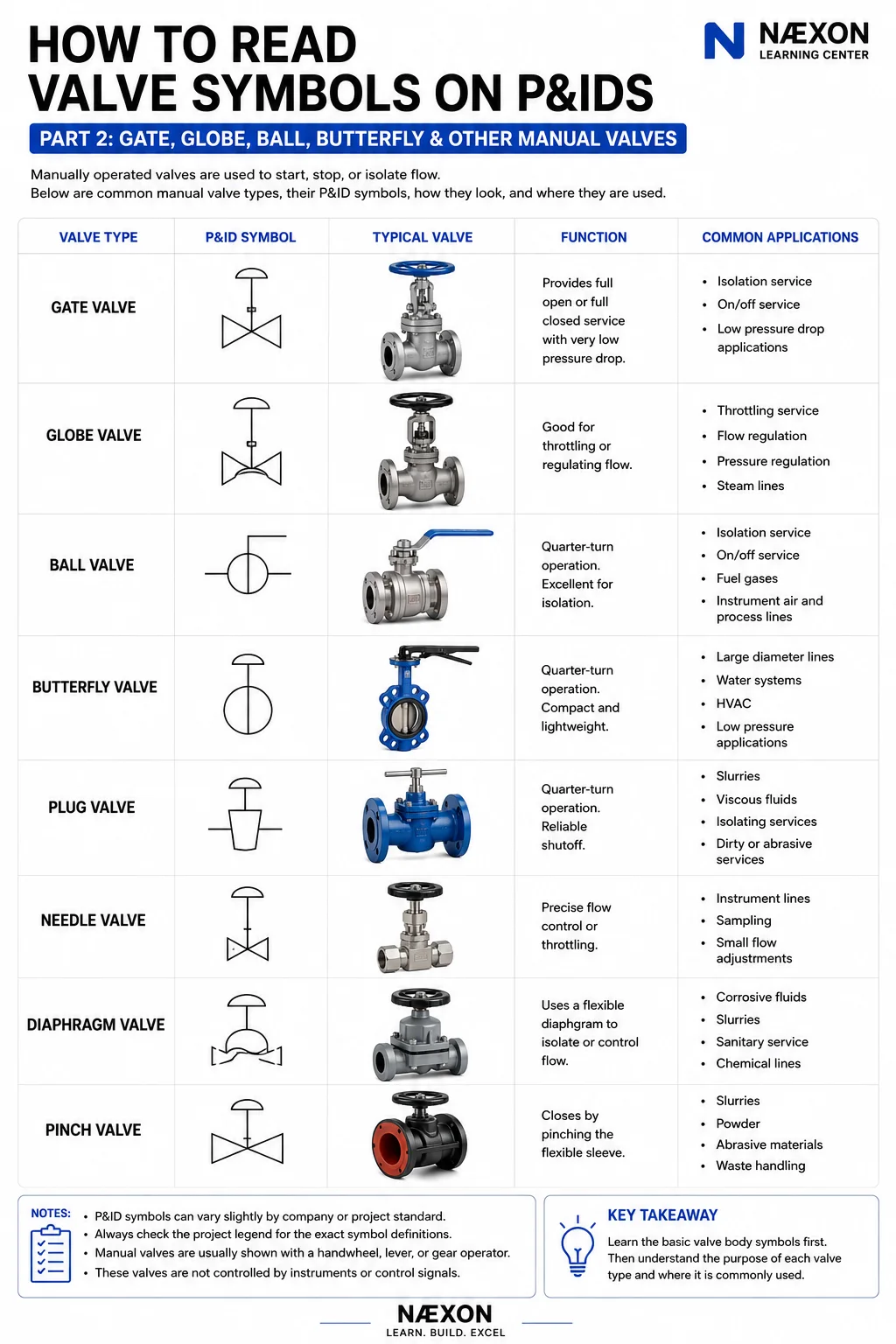
Read article →Part 2 applies a repeatable reading method to common manual valve symbols and their process functions.
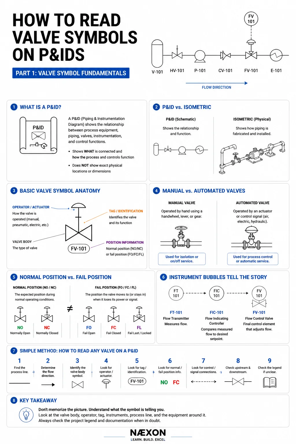
Read article →Part 1 introduces valve-symbol construction and a step-by-step method for approaching unfamiliar P&ID symbols without guessing.
Read article →Tungsten preparation changes TIG arc behavior. Compare sharper, moderate, and blunter grinds for different welding conditions.
Read article →Two-holing places bolt holes equally around the vertical centerline. Basic layout tools can establish that orientation when pins are unavailable.
Read article →Sling-angle geometry can sharply increase leg tension. Actual lifts must follow the approved plan, rated capacities, and qualified direction.
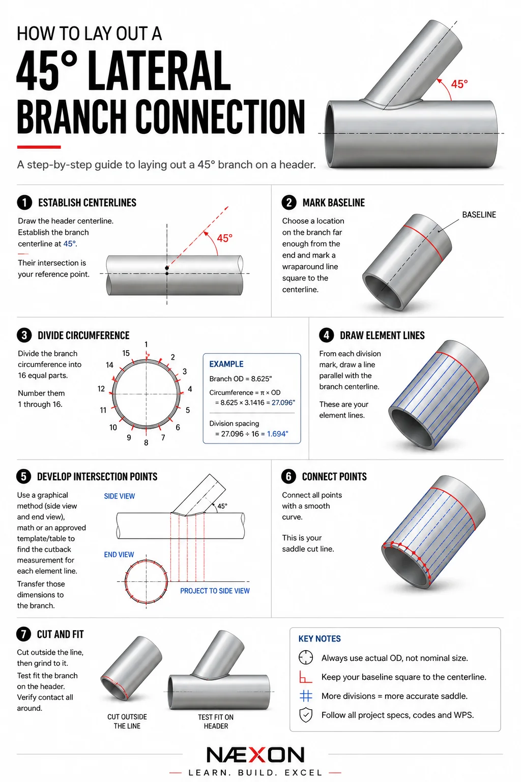
Read article →A 45° branch creates an asymmetrical intersection. This guide explains the field-layout principles behind developing the cut.
Read article →